|
Dla tego produktu nie napisano jeszcze recenzji!
 ;
Schematy są ale można wysilić się i zrobić kolorowy skan i o większej rozdzielczości. Wtedy schematy płytek będą czytelniejsze. Całość super jako wartość merytoryczna. Wszystkie dane potrzebne do podłączenia różnego rodzajów urządzeń takich gramofon, CD itd.
 ;
Szybko, sprawnie i tanio. Serwis godny polecenia. Będę polecał innym
;
Ogólnie jest OK, z wyjątkiem obrazu płyty głównej, który jest miejscami mało czytelny, ale można sobie poradzić.
;
Dokładna dokumentacja, pomogła w szybkiej naprawie telewizora. Dziękuję!
;
jedyne do czego mogę mieć zastrzeżenie to jakość zdjęć zawartych w przesłanej instrukcji serwisowej ponieważ są fatalnej jakości, praktycznie nieczytelne. tak poza tym jestem zadowolony to jest to czego szukałem.
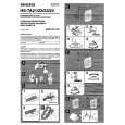
HOW TO MOVE THE CHASSIS INTO SERVICE POSITION
1. 2. 3. 4. 5. 6. 7. 8. Remove the bead clamper from the mains lead and attach to the degauss coil, shown in Fig.5. Hold and lift the rear of the E-PCB chassis and gently pull the chassis toward you, as shown in Fig.4. Release the respective wiring clips and rotate the chassis horizontally through 90°, anti-clockwise. Move the EHT lead around to the left side of the CRT neck. Elevate the front of the chassis. Clip the chassis frame onto the bead clamper, on the degauss coil, as shown in Fig.5. Locate the base of the chassis frame into the hole (marked A), shown in Fig.6. After servicing replace the bead clamper and ensure all wiring is returned to its original position before returning the receiver to the customer.
Fig.4.
Fig.5.
Fig.6. (A)
4
|