|
|
|
Kto jest w sklepie?
Sklep przegląda 5929 gości |
|
Kategorie
|
|
Informacje
|
|
Polecamy
|
|
|
 |
|
|
Dla tego produktu nie napisano jeszcze recenzji!
 ;
Wszystko w porządku.
Instrukcja czytelna i kompletna.
Dziękuję.
all right!
thank you.
;
Bardzo dobra instrukcja. Zawiera wszystko co potrzeba, polecam!
 ;
Instrukcja jest OK. Schematy czytelne, opisane niektóre procedury.
;
Instrukcja bardzo czytelna. zawiera co potrzeba. Polecam
;
...instrukcja serwisowa w pełni czytelna i kompletna. Dziękuję!
SAFETY PRECAUTIONS
GENERAL GUIDELINES
1. IMPORTANT SAFETY NOTICE There are special components used in this equipment which are important for safety. These parts are marked by in the Schematic Diagrams, Circuit Board Layout, Exploded Views and Replacement Parts List. It is essential that these critical parts should be replaced with manufacturer's specified parts to prevent X-RADIATION, shock, fire, or other hazards. Do not modify the original design without permission of manufacturer. 2. An Isolation Transformer should always be used during the servicing of Combination VCR whose chassis is not isolated from the AC power line. Use a transformer of adequate power rating as this protects the technician from accidents resulting in personal injury from electrical shocks. It will also protect Combination VCR from being damaged by accidental shorting that may occur during servicing. 3. When servicing, observe the original lead dress, especially the lead dress in the high voltage circuits. If a short circuit is found, replace all parts which have been overheated or damaged by the short circuit. 4. After servicing, see to it that all the protective devices such as insulation barriers, insulation papers, shield, and isolation R-C combinations are properly installed. 5. Before turning the receiver on, measure the resistance between B+ line and chassis ground. Connect (-) side of an ohmmeter to the B+ lines, and (+) side to chassis ground. Each line should have more resistance than specified, as follows : B+ Line Minimum Resistance 130V 1K ohm (Hot chassis ground) 27V 180 ohms (Cold chassis ground) 17V 110 ohms (Cold chassis ground) 6. When the TV set is not used for a long period of time, unplug the power cord from the AC outlet. 7. Potentials, as high as 25.0KV (Model: A, B, C, D, E) or 30.0KV (Model: F, I) or 29.0KV (Model: G, H) are present when this TV set is in operation. Operation of the TV set without the rear cover involves the danger of a shock hazard from the TV set power supply. Servicing should not be attempted by anyone who is not thoroughly familiar with the precautions necessary when working on high voltage equipment. Always discharge the anode of the picture tube to the CRT ground of receiver before handling the tube. 8. After servicing make the following leakage current checks to prevent the customer from being exposed to shock hazards.
LEAKAGE CURRENT HOT CHECK
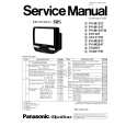
1. Plug the AC cord directly into the AC outlet. Do not use a isolation transformer for this check. 2. Connect a 1.5K ohms, 10 watts resistor, in parallel with a 0.15 micro farad capacitor, between each exposed metallic part on the set and a good earth ground , as shown in Figure 1. 3. Use an AC voltmeter, with 1000 ohms/volt or more sensitivity, to measure the potential across the resistor. 4. Check each exposed metallic part, and measure the voltage at each point. 5. Reverse the AC plug in the AC outlet and repeat each of the above measurements. 6. The potential at any point should not exceed 0.75 volt RMS. A leakage current tester (Simpson Model 229 equivalent) may be used to make the hot checks, leakage current must not exceed 1/2 milliampere. In case a measurement is outside of the limits specified, there is a possibility of shock hazard, and the receiver should be repaired and rechecked before it is returned to the customer.
Hot-Check Circuit AC VOLTMETER
0.15µF
TO APPLIANCES EXPOSED METAL PARTS EARTH GROUND
1500�. 10W
Figure 1
X-RADIATION
WARNING :
1. The potential source of X-Radiation in TV sets is the High Voltage section and the picture tube. 2. When using a picture tube test fixture for service, ensure that the fixture is capable of handling 25.0KV (Model: A, B, C, D, E) or 30.0KV (Model: F, I) or 29.0KV (Model: G, H) without causing X-Radiation. NOTE : It is important to use an accurate periodically calibrated high voltage meter. 1. Reduce the brightness to minimum. 2. Set the SERVICE switch to SERVICE . 3. Measure the High Voltage. The meter reading should indicate 23.5 +/- 1.5KV (Model: A, B, C, D, E) or 28.5 +/- 1.5KV (Model: F, I) or 27.5 +/- 1.5KV (Model: G, H). If the meter indication is out of tolerance, immediate service and correction is required to prevent the possibility of premature component failure. 4. To prevent an X-Radiation possibly, it is essential to use the specified picture tube.
LEAKAGE CURRENT COLD CHECK
1. Unplug the AC cord and connect a jumper between the two prongs on the plug. 2. For physically operated power switches, turn power on. Otherwise skip step 2. 3. Measure the resistance value, with an ohmmeter, between the jumpered AC plug and each exposed metallic cabinet part on the receiver, such as screwheads, connectors, etc. When the exposed metallic part has a return path to the chassis, the reading should be between 1 M ohm and 12 M ohms. When the exposed metal does not have a return path to the chassis, the reading must be infinity.
1-1
|
|
|
> |
|